This series of posts on the President Steam engine in Philadelphia has led me far further then I expected. It started off with a desire to expand my knowledge of an engine with William West links; to gain some knowledge that I could use in future talks about the Last Great Engineer. And now I find myself writing about probably one of the most significant Industrial Heritage sites in the USA. In this post I bridge the gap between the past and now with a description of the engine house, the structure that links today’s modern landscape with its history.
The remains of the President’s engine house stands in Allentown Philadelphia, a very long way from where I write this blog in Cornwall. Therefore I will use the words and images from Mark Connar’s excellent paper on the Ueberroth Zinc Mine to describe the structure.
The Engine House described
“The square shaped pumping engine house is built of Potsdam Sandstone and is three stories high with the first floor at the elevation of the air pumps and condenser, the second floor near the top of the cylinder, and the third at the level of
The engine house in 2017
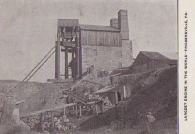
the beams. Overall the structure is 40 feet high. The north wall (called the “bob” wall in Cornish pump house design parlance), which supported the beams, is 9 feet thick with slots for the two flywheels, the south wall contains the cylinder opening, above which is the steam inlet and recesses for the two spring beams. This wall is also 9 feet thick and the other two walls (east and west) are 4.5 feet thick. Two square stacks that served the engine’s 16 boilers occupy the rear corners (face Old Bethlehem Pike). The boilers were housed in an adjoining building. The house plan is dominated by a central masonry platform, to which the engine was anchored, with large pits on either side for the flywheels and cranks.”
An indication of the sturdiness of this structure is that it sits on a rock formation 114 feet below ground surface and the foundation for the engine is thirty-two feet below the rock face. Another Cornishman named Simeon Noell was charged with the responsibility to oversee the engine house erection that commenced in 1868. Overall, the structure is very typical of engine houses that populate the Cornish and West Devon landscape in the United Kingdom.
The basic structural design is highly functional and little changed from the engine houses first built in the early decades of the 18th century. The President was a “house-built” engine in that the engine house was an integral part of the engine, supporting it rather than simply providing weather protection for equipment and staff. The foundation is sturdy; it had to be capable of withstanding the stresses the engine could produce. The “bob-wall” carried the main weight and thrust of the engine. The interior layout of the pumping engine house was a basic Cornish pattern. The first floor, or bottom chamber, was known as the “driving floor” because it accommodated the throttle and other controls. Here the engineers had access to the lower portion of the key equipment. The second floor or middle chamber allowed access to the cylinder head and upper valve chest. The third floor was called the “bobloft” was this level allowed access to the beam for servicing and also held tackling gear used to lift heavy parts of the pump when repairs were necessary.”
The Engine house today
“The current condition of the engine house is derelict. It is enclosed by a security fence and is overgrown with vegetation. The brick chimney stacks are no longer standing (I have observed this structure for over 50 years and do not recall ever seeing the brick stacks, however, they are visible in photographs from the 1930s and early 1940s). The structure is best viewed in the fall and winter when less obscured by vegetation. The pumping house is the only visible remains when viewed from outside the gated area, however, a report by Professor Miller of Lehigh University prepared in 1923 indicated that an office structure was also remaining on the site.” Mark Connar
This now seems to be an appropriate place to take a quick detour from the President Engine, and look at some Cornish engine houses over here in Cornwall for a comparison. So its time to start digging into some of the hidden depths of my laptop filing system and see what suitable images I have hidden away. So if you are reading this blog from across the pond please keep following, as I hope some of the photos may hint at the potential of this amazing building hidden away in Philadelphia.
The engine house featuring on the cover of the Kindle Edition of William West of Tredenham is that of the famous Austen’s Engine at Fowey Consols, in mid-Cornwall. This 80″ engine was fitted with a lattice beam similar to the one used by the President,
Now this series of posts on John West’s massive steam engine arrives at the point where it digs into the technical details. I have extracted various facts from the Damian Nance’s article, sifted, sorted and summarised to give a summary of the engine.
What was the President Engine?
The President was a rotative double acting engine with a 110″ cylinder, a 10 foot stroke and weight of 675 tons Although described as a Cornish engine, but had many features not common to pumping engines in Cornwall, i.e. it was rotative had flywheels, and was double acting.
The engine was named after president Ulysses S. Grant, who had been invited to its dedication but then failed to arrive.
Who built the engine?
The Cornish Engineer John West built the engine (the nephew of William West, the Last Great Cornish Engineer), and its components were built by various companies in Eastern USA. Merrick and sons built the engine at their Southwark factory Philadelphia, but much of the casting was done at Lazell Perkins and co Bridgewater Massachusetts. The Pumps, boilers and mountings were produced by LP Morris and co, Philadelphia.
The engine was built to pump large quantities of water from a relatively shallow mine shaft. Accounts of the engine differ in the number of pumps installed. Some state two pair, some three. Each pair of pumps consisted of a lifting pump at the bottom of the shaft, and a 30″ plunger pump part way up. The lifting pumps were only at a depth of 127 feet, very shallow compared to the Cornish mines of the time which were down to thousands of feet deep. The engine pumped at 15000 gallons per minute at 12 strokes per minute, and discharged into an adit and into a tank for use as boiler and condenser feed-water.
How was the steam provided?
The three roofs of the boiler house.
An engine of this size demanded large quantities of steam, and so it had an impressive array of boilers. The President was served by 16 boilers in a boiler house to the rear of the engine house, each boiler was 50 feet long with a 36 inch diameter.
The engine was designed to run at 60 psi at which pressure it produced 3000 horsepower, although in use it was normally run at a lower pressure.
What was the key features of the President Engine?
Apart from its sheer size the President had several interesting features that set it apart from the standard arrangement of a pumping engine back in Cornwall. These differences arose from the shallow depth of the mine. Engines running expensively on the Cornish cycle are more effective if they have a load of the heavy pump rods in the shaft. To replace this John West designed the engine with large 92 ton flywheels of over 30 foot diameter. For smoother operation of the flywheel West made the engine double acting (powered on both up and down strokes).
Note: The weight and diameter of the flywheel has been shown differently on some engine descriptions.These figures have been confirmed as the most likely to be correct by Mark Connar, who I thank for the additional information.
Although he installed Cornish style steam valves, the operating method was unusual. Valve operation was through cams fitted on the flywheel shaft, three cams for three different values of cut-off. The throttle valve was fitted with an automatic control using a block of wood in the sump of the shaft connected by wire to the valve. An ingenious arrangement that allowed more steam to enter the engine as the water level rose.
The lattice beams
These are the features that attracted me to the engine. Although Open-work beams are graceful and light, they did not become widely adopted. Their main user was John West’s Uncle, William West of Tredenham. All of his most important engines used this design, and it is no doubt the family influence that resulted in their distinctive form being adopted for the President.

 The President Engine House
An indication of the sturdiness of this structure is that it sits on a rock formation 114 feet below ground surface and the foundation for the engine is thirty-two feet below the rock face. Another Cornishman named Simeon Noell was charged with the responsibility to oversee the engine house erection that commenced in 1868. Overall, the structure is very typical of engine houses that populate the Cornish and West Devon landscape in the United Kingdom.
houses first built in the early decades of the 18th century. The President was a “house-built” engine in that the engine house was an integral part of the engine, supporting it rather than simply providing weather protection for equipment and staff. The foundation is sturdy; it had to be capable of withstanding the stresses the engine could produce. The “bob-wall” carried the main weight and thrust of the engine. The interior layout of the pumping engine house was a basic Cornish pattern. The first floor, or bottom chamber, was known as the “driving floor” because it accommodated the throttle and other controls. Here the engineers had access to the lower portion of the key equipment. The second floor or middle chamber allowed access to the cylinder head and upper valve chest. The third floor was called the “bobloft” was this level allowed access to the beam for servicing and also held tackling gear used to lift heavy parts of the pump when repairs were necessary.”

fence and is overgrown with vegetation. The brick chimney stacks are no longer standing (I have observed this structure for over 50 years and do not recall ever seeing the brick stacks, however, they are visible in photographs from the 1930s and early 1940s). The structure is best viewed in the fall and winter when less obscured by vegetation. The pumping house is the only visible remains when viewed from outside the gated area, however, a report by Professor Miller of Lehigh University prepared in 1923 indicated that an office structure was also remaining on the site.” Mark Connar

 and weight of 675 tons Although described as a Cornish engine, but had many features not common to pumping engines in Cornwall, i.e. it was rotative had flywheels, and was double acting.


